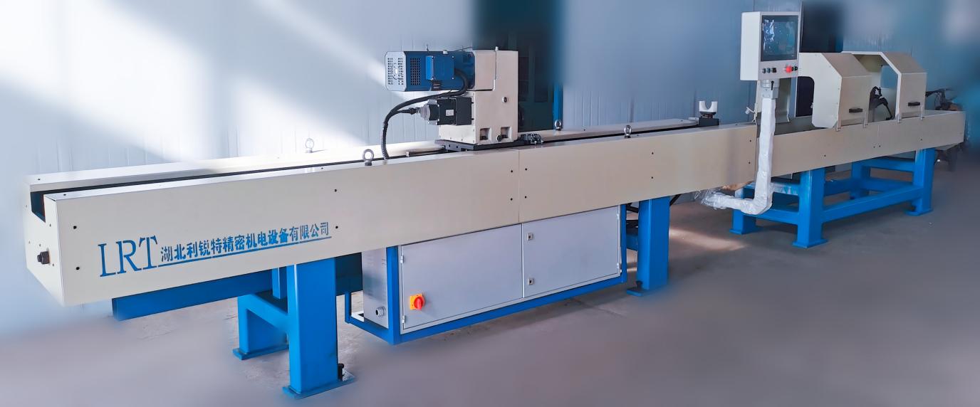
(Picture of QWH honing machine)
Main technical parameters
Total power of machine tool: 13.5KW
V-shaped quick assembly fixture 60-400mm
Split V-shaped fixture 400-620mm
Processing rhythm: average: 300-550cm3/h, maximum: 700 cm3/h
Dimensional accuracy: H6-H8
Roundness: 0.01mm-0.04mm
Roughness: Ra0.2 Ra0.4
1.1 Machine Tool Parameter Table
| model |
STROKE LENGTH(MM) |
machine range
(MM) |
Machine length(MM) |
Machine width(MM) |
Machine height(MM) |
weight(KG) |
| QWH-1000 |
1000 |
Φ30-φ560 |
5024 |
1000 |
1000 |
3100 |
| QWH-2000 |
2000 |
Φ30-φ560 |
7024 |
1000 |
1000 |
3100 |
| QWH-3000 |
3000 |
Φ30-φ560 |
9024 |
1000 |
1000 |
3800 |
| QWH-5000 |
5000 |
Φ30-φ560 |
13540 |
1000 |
1000 |
5800 |
| QWH-8000 |
8000 |
Φ30-φ560 |
19540 |
1000 |
1000 |
6200 |
| QWH-10000 |
10000 |
Φ30-φ560 |
23540 |
1000 |
1000 |
7500 |
1.2 CNC system human-machine interface
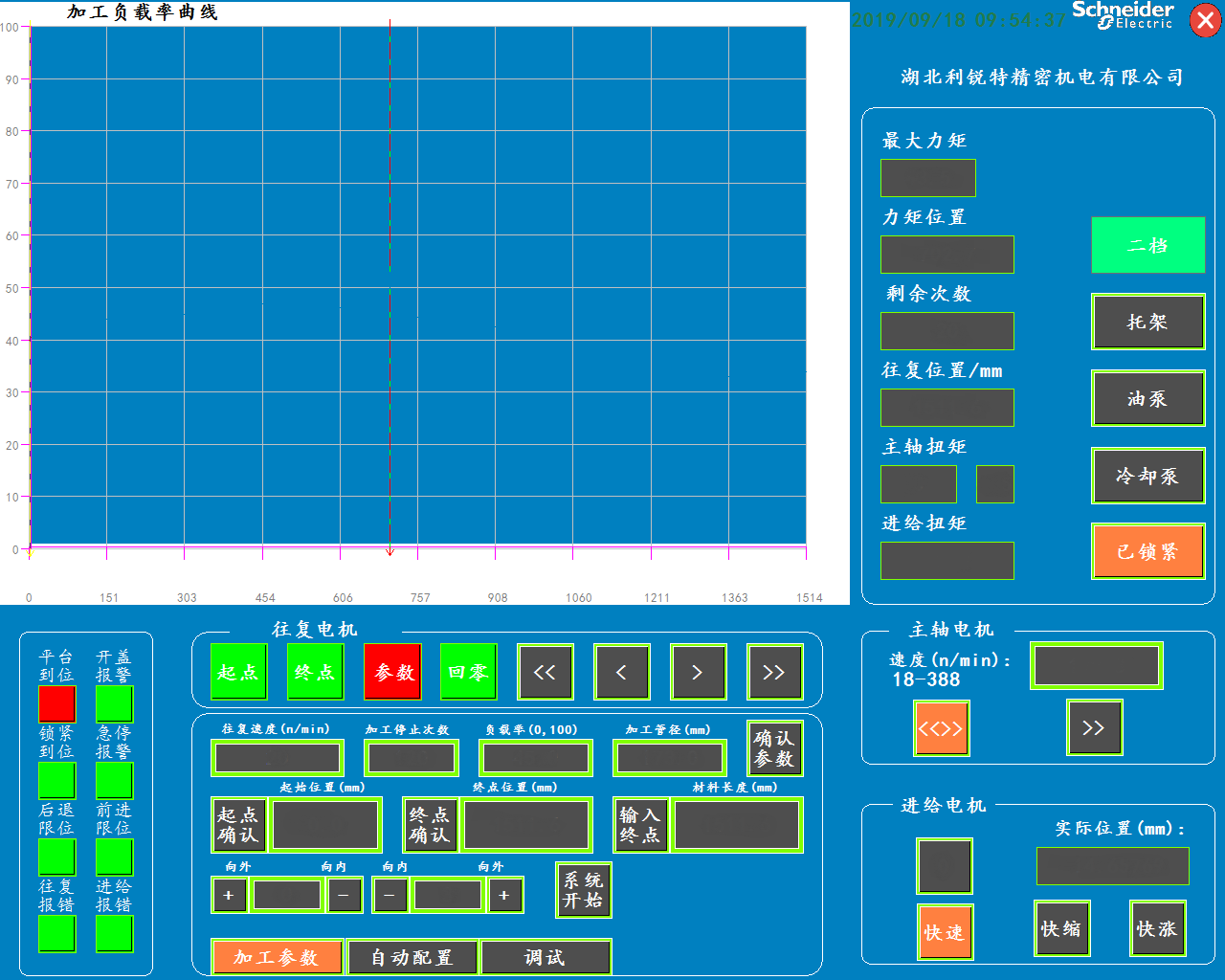
The human-machine interface includes several parts: processing load rate curve, data display and switch control, alarm status monitoring, motor manual control, and parameter configuration. As shown in the following figure:

圖1 interface
Processing load rate curve
The X-axis is the real-time position of the reciprocating motor, the Y-axis is the load rate of the feed motor, and the position of the point with the highest load rate of the motor is displayed in real-time for each cycle of reciprocating motion (shown by the black vertical line). The two ends of the X-axis are the starting and ending points of the set reciprocating stroke, and the load rate range of the Y-axis is 0-100%. The higher the load rate, the higher the grinding efficiency. For workpieces with different diameters and materials, it should be noted that the load rate should not be set too high, The amplitude modification should not be too large to avoid damaging the spindle gearbox.
Data display and switch control
On the left is the real-time display of system dynamic data, where the torque is the output torque of the spindle rotation motor. This system adopts redundant design and collects feedback torque signals from the spindle servo motor and simulated torque signals from high-precision torque sensors loaded in the spindle box. The system integrates these two sets of signals to improve processing accuracy. The feed torque of the feed motor is displayed at the bottom. To protect the reducer in the spindle box, the system will automatically enter the protection mode when the torque of the feed motor is too large; On the right is a virtual jog switch, including a bracket, oil pump, cooling pump, locking device, etc. These switches can be linked with the processing process without human intervention. They are used for forced action in special circumstances. The locking device automatically locks when the platform is in place, and the bracket automatically extends after processing, and the pump automatically stops. During the automatic operation process, the bracket switch and locking device switch will automatically shield to avoid malfunctions caused by misoperation, until the automatic operation is completed and the shield is released.
Alarm status
Real time monitoring of system status, with red light indicating alarm and green light indicating safety. Before processing the workpiece, it is necessary to confirm whether the status alarm lights are all green. When dangerous signals such as current rear limit and emergency stop are generated, the machine should be turned off in a timely manner. After troubleshooting, the machine can only be powered on and restarted for normal operation.
Motor manual control
All motors of the control system can be manually controlled through virtual buttons, and they are all inching type. Release the button to immediately stop the motor, ensuring safe operation. The manual button of the reciprocating motor can be used for the "timely reversing" function during automatic machining operation, which is used to change the reversing position of the reciprocating motor in real time (detailed in the operation method later).
Processing parameter configuration
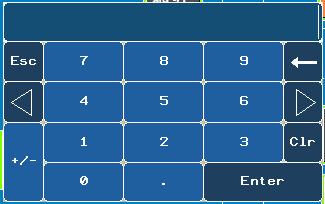
The setting of processing parameters is divided into four steps: setting the start point, setting the end point, parameter configuration, and motor return to zero. It can be operated sequentially according to the prompts of the middle four status lights. There are two ways to set the end point: "manual setting" and "direct input". Below the parameter configuration is the "Increase/Decrease Travel" function. It can dynamically change the starting and ending point positions during the workpiece processing process. The parameter input in the parameter input box adopts a virtual number keyboard. When double clicking on the input box, the virtual number keyboard is activated. After inputting the numbers, click the "Enter" OK key to complete the parameter settings in the input box. The virtual number keyboard is shown in the following figure:

圖2 Virtual Number Keyboard
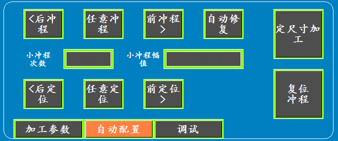
Automatic configuration
It can achieve manual and automatic repair functions, used to repair high points on the cylinder wall. By using virtual buttons to repair around any point according to the set amplitude, the system automatically recognizes the highest point on the cylinder wall, and repairs around the highest point according to the set amplitude, making the processing process more intelligent. Below is the "Positioning and Repair" function, which allows the honing head to be fixed at any point and rotated in place. Click to take effect, and then click again to cancel this function. The button at the bottom right is used to achieve "fixed size repair", which is used to maintain a certain feed rate of the honing head. This function can be used in conjunction with the feed motor to manually tighten. The automatic configuration is shown in the following figure:


